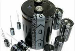
高压电解电容560UF/450V
| 价 格: | 17.00 | |
| 型号/规格: | 35*70 560UF/450V | |
| 品牌/商标: | SF | |
| 环保类别: | 无铅环保型 | |
| 安装方式: | 直插式 | |
| 包装方式: | 散装 | |
| 产品主要用途: | 工业电力电气设备 | |
| 引出线类型: | 螺栓型 | |
| 特征: | 圆柱体型 | |
| 标称容量范围: | 560 | |
| 额定电压范围: | 450 | |
| 温度系数范围: | -40/+105 |
东莞市双飞电子有限公司
FEATURES 特点
1. Rated Working Voltage Range 6.3 to 100VCD/160 to 450VCD at Operation Temperature Range –40 to +105℃/-25
to +105℃.
额定工作电压及工作环境温度范围分别为6.3~100VDC/–40+105℃,160~450VDC/-25+105℃.
2. This series is for communication equipments, switching power supply, industrial measuring instruments, automotive electric products, etc.
适应于通讯设备、开关电源、工业测试机及各种自动化电子产品中。
SPECIFICATIONS 规格表
|
Item 项目 |
Performance characteristics 主要特性 |
|||||||||||||||||||||||||||||||
|
Rated Working Voltage Range 额定工作电压范围 |
6.3 to 100V DC |
160 to 450V DC |
||||||||||||||||||||||||||||||
|
Operation Temperature Range 使用温度范围 |
-40 to +105℃ |
-25 to +105℃ |
||||||||||||||||||||||||||||||
|
Nominal Capacitance Range 标称容量 |
0.1 to 33000μF |
|||||||||||||||||||||||||||||||
|
Capacitance Tolerance 电容量允许偏差 |
±20%(120Hz,+20℃) |
|||||||||||||||||||||||||||||||
|
Leakage Current 低温特性 |
1≤0.01CV or 3(μA) after 2 minutes whichever is greater measured with rated working voltage applied at +20℃ 20℃.升到额定电压后两分钟时读数.取较大者. |
1≤0.03CV +40(μA) after 2 minutes application of rated working voltage at +20℃ 20℃.升到额定电压后两分钟时读数. |
||||||||||||||||||||||||||||||
|
Dissipation Factor tanδ (120Hz,+20℃) 损耗角正切值tanδ |
Working voltage(V) 工作电压 |
6.3 |
10 |
16 |
25 |
35 |
50 |
63 |
100 |
|||||||||||||||||||||||
|
tanδ(max.) |
0.28 |
0.24 |
0.20 |
0.16 |
0.14 |
0.12 |
0.10 |
0.08 |
||||||||||||||||||||||||
|
Working voltage(V) 工作电压 |
160 |
200 |
250 |
350 |
400 |
450 |
||||||||||||||||||||||||||
|
tanδ(max.) |
0.20 |
0.20 |
0.20 |
0.25 |
0.25 |
0.25 |
||||||||||||||||||||||||||
|
For capacitance value >1000μF, add 0.02 per another 1000μF 对容量大于1000μF者,每增加1000μF,DF增加0.02 |
||||||||||||||||||||||||||||||||
|
Ripple Current 纹波电流 |
Refer to standard products table (120Hz,85℃) 专指标准产品(120Hz,85℃). Correction factor for frequency 标准产品频率调整系数 |
|||||||||||||||||||||||||||||||
|
Voltage(V) |
Capacitance Range(μF) |
50Hz |
120Hz |
300Hz |
1kHz |
10kHz~ |
||||||||||||||||||||||||||
|
6.3~100 |
~47 |
0.75 |
1.00 |
1.35 |
1.57 |
2.00 |
||||||||||||||||||||||||||
|
100~470 |
0.80 |
1.00 |
1.23 |
1.34 |
1.50 |
|||||||||||||||||||||||||||
|
1000~33000 |
0.85 |
1.00 |
0.10 |
0.13 |
1.15 |
|||||||||||||||||||||||||||
|
160~450 |
0.47~220 |
0.80 |
1.00 |
0.25 |
1.40 |
1.60 |
||||||||||||||||||||||||||
|
330~1000 |
0.90 |
1.00 |
0.10 |
0.13 |
1.15 |
|||||||||||||||||||||||||||
|
Low Temperature Characteristics 低温特性
Low Temperature Characteristics 低温特性 |
Impedance ratio max. at 120Hz 120Hz时的阻抗比率. |
|||||||||||||||||||||||||||||||
|
Working voltage(V) |
6.3 |
10 |
16 |
25 |
35 |
50 |
63 |
100 |
||||||||||||||||||||||||
|
Z-25℃/ Z+20℃ |
5 |
4 |
3 |
2 |
2 |
2 |
2 |
2 |
||||||||||||||||||||||||
|
Z-40℃/ Z+20℃ |
10 |
8 |
6 |
4 |
3 |
3 |
3 |
3 |
||||||||||||||||||||||||
|
Working voltage(V) |
160 |
200 |
250 |
350 |
400 |
450 |
||||||||||||||||||||||||||
|
Z-25℃/ Z+20℃ |
3 |
3 |
4 |
4 |
6 |
15 |
||||||||||||||||||||||||||
|
For capacitance value>1000μF, Add 0.5 per another 1000μF for Z-25℃/ Z+20℃ Add 1.0 per another 1000μF for Z-40℃/ Z+20 对容量大于1000μF者,每增加1000μF. Z-25℃/ Z+20℃增加0.5 对容量大于1000μF者,每增加1000μF. Z-40℃/ Z+20增加1. |
||||||||||||||||||||||||||||||||
|
High Temperature Loading 高温负荷 |
Test conditions 试验条件 Duration : 1000 hours Ambient temperature : +105℃ Applied voltage : DC voltage with maximum permissible ripple current specified at +105℃(Sum of the DC voltage and super-imposed peak AC voltage for maximum permissible ripple current should be equal to rated DC working voltage). 105℃时施加允许纹波电流的直流电压 (施加的直流电压与纹波电流下对应的交流峰值电压之和不得超过电容器的额定工作电压)。 Post test requirements at +20℃ 试验完毕在20℃测试应满足 Leakage current : ≤Initial specified value Capacitance change : ≤±20% of initial measured value tan δ : ≤200% of initial specified value |
|||||||||||||||||||||||||||||||
|
Shelf Life 贮存寿命 |
Test conditions 试验条件 Duration : 1000 hours Ambient temperature : +105℃ Applied voltage : (None) Post test requirements at +20℃ 试验完毕在20℃测试应满足 Leakage current : ≤200%Initial specified value Capacitance change : ≤±20% of initial measured value tan δ : ≤200% of initial specified value |
|||||||||||||||||||||||||||||||
|
Others 其它 |
JIS C-5141 JIS C-5102 |
|||||||||||||||||||||||||||||||
CASE SIZE TABLE
|
|
高压贴片电容1812 450V
信息内容:TDK贴片电容选型 1.利用贴片陶瓷电容器介质层的薄层化和多层叠层技术,使电容值大为扩大 2.单片结构保证有的机械性强度及可靠性 3.极高的精确度,在进行自动装配时有高度的准确性 4.因仅有陶瓷和金属构成,故即便在高温,低温环境下亦无渐衰的现象出现,具有较强可靠性与稳定性 5.低集散电容的特性可完成接近理论值的电路设计 6.残留诱导系数小,确保上佳的频率特性 7.因电解电容器领域也获得了电容,故使用寿命延长,更造于具有高可靠性的电源 8.由于ESR低,频率特性良好,故最适合于高频,高密度类型的电源 工作温度范围: -55~125℃ 额定电压: 100VDC~3000VDC 温度特性: NPO:≤±30ppm/℃,-55~125℃(EIA Class I) X7R:≤±15%,-55~125℃(EIA Class II) 容量范围: NPO:2pF to 100nF;X7R:150pF to 2.2uF 损失角正切(tanδ): NPO:Q≥1000;X7R:D.F.≤2.5% 绝缘电阻: 10GΩ 或 500/C Ω 取两者最小值 老化速率: NPO:1%;X7R:2.5% 一个decade时间 介质电耐电压: 100V ≤ V <500V :200% 额定电压 500V ≤ V <1000V :150%额定电压 1000v≤ V :120%额定电压 TDK 原装新货大量供应,现货库存,价格有优...
供应插件电解电容10*16 4.7UF/450V
信息内容:电解电容是电容的一种介质有电解液涂层有极性,分正负不可接错。电容(Electric capacity),由两个金属极,中间夹有绝缘材料(介质)构成。 电解电容器特点一:单位体积的电容量非常大,比其它种类的电容大几十到数百倍。 电解电容器特点二:额定的容量可以做到非常大,可以轻易做到几万μf甚至几f(但不能和双电层电容比)。 电解电容器特点三:价格比其它种类具有压倒性优势,因为电解电容的组成材料都是普通的工业材料,比如铝等等。制造电解电容的设备也都是普通的工业设备,可以大规模生产,成本相对比较低。 电解电容器通常是由金属箔(铝/钽)作为正电极,金属箔的绝缘氧化层(氧化铝/钽五氧化物)作为电介质,电解电容器以其正电极的不同分为铝电解电容器和钽电解电容器。铝电解电容器的负电极由浸过电解质液(液态电解质)的薄纸/薄膜或电解质聚合物构成;钽电解电容器的负电极通常采用二氧化锰。由于均以电解质作为负电极(注意和电介质区分),电解电容器因而得名。 有极性电解电容器通常在电源电路或中频、低频电路中起电源滤波、退耦、信号耦合及时间常数设定、隔直流等作用。一般不能用于交流电源电路,在直流电源电路中作滤波电...


