供应 ST电机驱动芯片 L298N
| 价 格: | 面议 | |
| 品牌/商标: | STM |
DESCRIPTION
The L298 is an integrated monolithic circuit in a 15-
lead Multiwatt and PowerSO20 packages. It is a
high voltage, high current dual full-bridge driver de-
signed to accept standardTTL logic levels and drive
inductive loads such as relays, solenoids, DC and
stepping motors. Two enableinputs are provided to
enable or disable the deviceindependentlyof the in-
put signals. The emitters of the lower transistors of
each bridge are connected together and the corre-
sponding external terminal can be used for the con-nectionof an externalsensing resistor. An additional
supply input is provided so that the logic works at a
lower voltage.
APPLICATION INFORMATION (Refer to the block diagram)
1.1. POWER OUTPUT STAGE
The L298integratestwo poweroutputstages(A ; B).
The power output stage is a bridge configuration
and its outputs can drive an inductive load in com-
mon or differenzial mode, dependingon the state of
the inputs. The current that flows through the load
comes out from the bridge at the sense output : an
external resistor (RSA ; RSB.) allows to detect the in-
tensity of this current.
1.2. INPUT STAGE
Each bridge is driven by means of four gates the in-
put of which are In1 ; In2 ; EnA and In3 ; In4 ; EnB.
The In inputs set the bridge state when The En input
is high ; a lowstate of the En inputinhibitsthe bridge.
All the inputs are TTL compatible.
2. SUGGESTIONS
A non inductive capacitor, usually of 100 nF, must
be foreseen between both Vs and Vss, to ground,
as near as possible to GND pin. When the large ca-
pacitor of the power supply is too far from the IC, a
second smaller one must be foreseen near the
L298.
The sense resistor, not of a wire wound type, must
be grounded near the negative pole of Vs that must
be near the GND pin of the I.C.
Each input must be connected to the source of the
driving signals by means of a very short path.
Turn-On and Turn-Off : Before to Turn-ON the Sup-
ply Voltageand beforeto Turnit OFF, the Enablein-
put must be driven to the Low state.
3. APPLICATIONS
Fig 6 shows a bidirectional DC motor control Sche-
matic Diagram for which only one bridge is needed.
The external bridge of diodes D1 to D4 is made by
four fast recovery elements (trr??≤?200 nsec) that
must be chosen of a VF as low as possible at the
worst case of the load current.
The sense outputvoltage can be used to control the
current amplitude by chopping the inputs, or to pro-
vide overcurrent protection by switching low the en-
able input.
The brake function (Fast motor stop) requires that
the Absolute Maximum Rating of 2 Amps must
never be overcome.
When the repetitive peak current needed from the
load is higher than 2 Amps, a paralleled configura-
tion can be chosen (See Fig.7).
An external bridge of diodes are required when in-
ductive loads are driven and when the inputs of the
IC are chopped; Shottkydiodeswould be preferred.
This solution can drive until 3 Amps In DC operation
and until 3.5 Amps of a repetitive peak current.
OnFig 8 it is shownthe driving ofa twophasebipolar
stepper motor ; the needed signals to drive the in-
puts of the L298 are generated, in this example,
from the IC L297.
Fig 9 shows an example of P.C.B. designed for the
application of Fig 8.
Fig 10 shows a second two phase bipolar stepper
motor control circuit where the current is controlled
by the I.C. L6506.
dzsc/13/4515/13451558.jpg
dzsc/13/4515/13451558.jpgdzsc/13/4515/13451558.jpgdzsc/13/4515/13451558.jpgdzsc/13/4515/13451558.jpgdzsc/13/4515/13451558.jpgdzsc/13/4515/13451558.jpgdzsc/13/4515/13451558.jpgdzsc/13/4515/13451558.jpgdzsc/13/4515/13451558.jpgdzsc/13/4515/13451558.jpgdzsc/13/4515/13451558.jpgdzsc/13/4515/13451558.jpgdzsc/13/4515/13451558.jpgdzsc/13/4515/13451558.jpgdzsc/13/4515/13451558.jpgdzsc/13/4515/13451558.jpgdzsc/13/4515/13451558.jpgdzsc/13/4515/13451558.jpgdzsc/13/4515/13451558.jpgdzsc/13/4515/13451558.jpg
供应 单极霍尔开关 A01L 柜台现货
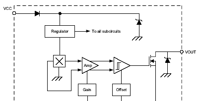
信息内容:dzsc/13/4515/13451559.jpg Features and Benefits Continuous-time operation Fast power-on time Low noise Stable operation over full operating temperature range Reverse battery protection Solid-state reliability Factory-programmed at end-of-line for optimum performance Robust EMC performance High ESD rating Regulator stability without a bypass capacitor dzsc/13/4515/13451559.jpg Description The Allegro® A1101-A1104 and A1106 Hall-effect switches are next generation replacements for the popular Allegro 312x and 314x lines of unipolar switches. The A110x family, produced with BiCMOS technology, consists of devices that feature fast power-on time and low-noise operation. Device programming is performed after packaging, to ensure increased switchpoint accuracy by eliminating offsets that can be induced by package stress. Unique Hall element geometries and low-offset amplifiers help to minimize noise and to reduce the residual offset voltage normally c...
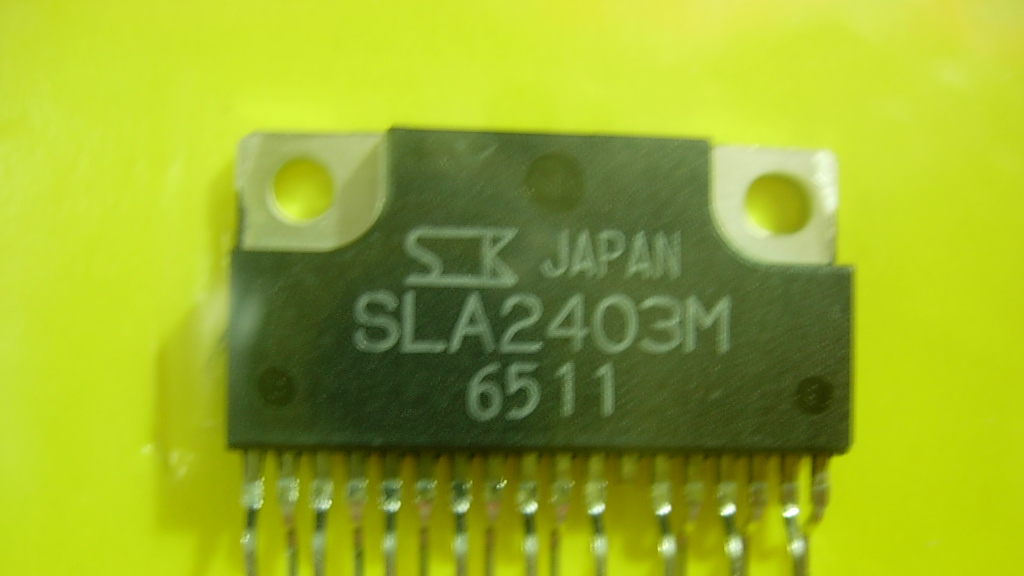
供应 汽车HTD驱动IC SLA2403M
信息内容:dzsc/13/4515/13451560.jpg dzsc/13/4515/13451560.jpg 应用:汽车HTD大灯开发IC,功能强大,性能稳定,用与超薄型


