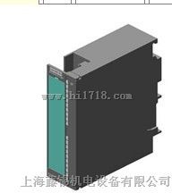
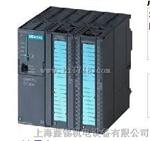
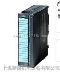
西门子SM335快速模拟量模块 西门子S7-300SM335 西门子SM335模块. 6ES7335-7HG01-0AB0
上海腾希电气技术有限公司(西门子授权代理商)
联系人 :吴 康( 销售经理 )24小时销售技术服务热线57
电话( Tel ): 传真( Fax ):
邮箱( Email )::@qq.com 商务( Q Q ) :
网址 ( Web ) : https://www.tensey.com/
地址( Add ):上海市松江区松乐路128号月厦新天地1021-1022
上海腾希电器技术有限公司经营西门子系列产品 承若质量保证,欢迎您来电咨询高品质西门子驱动和自动化产品价格S7-200 S7-300 S7-400 S7-1200 触摸屏,变频器,6FC,6SN S120 V10 V60 V80 伺服数控备件:各类电动机:原装进口电机(1LA7、1LG4、1LA9、1LE1),国产电机(1LG0,1LE0);专用电机,大型电机(1LA8,1LA4,1PQ8);伺服电机(1PH,1PM,1FT,1FK,1FS)西门子保内全新原装产品!质保一年!一年内因产品本身质量问题更换新产品,不收取任何费
西门子SM335快速模拟量模块 西门子S7-300SM335 西门子SM335模块.
SM 335 快速模拟 I / O 模块
- 将过程的模拟信号转换成用于 SIMATIC S7-300 的数字值
- 将 SIMATIC S7-300 数字信号转换成用于过程的模拟信号。
另外,模块可为编码器(例如,线性电位计)供应 10 V / 25 mA 的电源,并且它有一个计数器输入。通过计数器输入可在已知间隔时间内覆盖的通路长度,或可记录简单旋转传感器信号,且速度可以通过时间间隔计算时,就可确定速度。
SM 335 快速模拟量输入 / 输出模块具有以下机械特征:
- 紧凑式设计;硬质塑料外壳包含有一个放在前面板后面保护起来的前连接器的连接以及在前部面板门上的标签区域。
- 易于安装;模块安装在标准导轨上并通过总线连接器与相邻的模块连接。
- 用户友好布线;这些模块的布线是通过两个插入式前面板连接器实现的。初插入时,插销中的编码机构会锁定就位。这便确保了连接器只能装在同种类型的模块上。如果更换了模块,则在已完全接好线的同种类型的模块上可使用前连接器。
- 用于 24 V 电源的干扰抑制滤波器:干扰抑制滤波器屏蔽对 SM 335 的高频干扰以免影响 SM335 的正常功能。滤波器与用于 SM 335 的 24 V 电源电路相连并且可保护多 4 个 SM 335 模块。滤波器必须单独订购。干扰抑制滤波器被强制达到 SIMATIC S7 标准规定的抗噪音水平。
SM 335 快速模拟量输入/输出模块提供:
- 4 个快速模拟输入(用于4 通道的基本转换时间多为 1 ms)
- 4 个快速模拟量输出(每个通道的转换时间多为 0.8 ms)
- 编码器电源 10 V/25 mA
- 1 个计数器输入(24 V/500 Hz)
SM 335 有两种特殊方式:
- 比较器:在这种方式下,SM 335 会拿设定点值与模拟输入时测量的模拟值作比较。应用:非常快速地比较模拟值
- 仅测量:在“仅测量”方式下,不断地测量模拟输入而不更新模拟量输出。应用:非常快速地测量模拟值(< 0.5 ms)
更多的信息可在 SM 335 手册中找到(通过 Internet )
http://www.ad.siemens.de/mc/html_76/products/index.htm
SM 335 | |
|---|---|
Module-specific data | |
Number of inputs | 4 |
Number of outputs | 4 |
Cable length, shielded | 200 m |
With wire-break monitoring in range 0 V to 10 V | 30 m |
Voltages, currents, potentials | |
Rated load voltage | 24 V DC |
Polarity reversal protection | yes |
Galvanic isolation | yes |
Permissible potential difference | |
? between inputs (UCM) | 3 V |
? between input (M terminal) and central grounding point | 75 V DC |
? Insulation | tested at 500 V DC |
Current consumption | |
? from S7-300 backplane bus, max. | 75 mA |
? from L+, max. | 150 mA |
Power losses, max. | 3.6 W |
Status, interrupts, diagnostics | |
Interrupts | |
? Limit value interrupt | no |
? Cycle end interrupt | yes, parameterizable |
? Diagnostics interrupt | yes, parameterizable |
Diagnostic functions | |
? Fault display for grouped fault | yes, red LED |
? Diagnostic information can be read out | yes |
Analog value generation for inputs | |
Measuring principle | successive approximation |
Conversion time per channel | 200 μs |
? Basic conversion time for 4 channels, max. | 1 ms |
Resolution | |
? Bipolar | 13 bits + sign |
? Unipolar | 14 bits |
Analog inputs | |
Interference between inputs | |
? at 50 Hz | 65 dB |
? at 60 Hz | 65 dB |
Operational limits (over entire temperature range, referred to input range) | |
? with voltage measurement | ± 0.15 % (with 14-bit resolution) |
? with current measurement | 0.25 % |
Basic error limit (operational limits at 25 °C, referred to input range) | 0.13 % (with 14-bit resolution) |
Temperature error (referred to input range) | ± 0.1 % (with 14-bit resolution) |
Linearity error (referred to input range) | ± 0.015 % |
Repeatability (under steady-state conditions, at 25 °C, referred to input range) | ± 0.05 % |
Encoder selection data | |
Input range (rated values)/input resistance | |
? Voltage | ± 1 V; ± 10 V; ± 2.5 V; 0 V to 2 V; 0 V to 10 V: 10 MΩ |
? Current | ± 10 mA; 0 mA to 20 mA; 4 mA to 20 mA: 100 Ω |
Permissible input voltage for voltage input (destruction limit) | ± 30 V |
Permissible input current for current input (destruction limit) | 25 mA |
Connection of signal encoder | |
? for voltage measurement | possible |
? for current measurement | |
- as 2-wire transducer | not possible |
- as 4-wire transducer | possible |
? for resistance measurement | not possible |
Output for supplying the transducer (short-circuit proof) | 10 V/25 mA |
Data for encoder supply output | |
Rated voltage | 10 V |
Output current, max. | 25 mA |
Short-circuit proof | yes |
Operating limits (over entire temperature range) | 0.2 % |
Temperature error | 0.002 %/K |
Basic error for rated voltage | 0.1 % |
Outputs | |
Resolution(including overcontrol range) | |
? ± 10 V | 11 bits + sign |
? from 0 V to 10 V | 12 bits |
Conversion time per channel, max. | 800 μs |
Settling time | |
? for resistive load | < 0.1 ms |
? for capacitive load | < 3.3 ms |
? for inductive load | < 0.5 ms |
Interference between outputs | 40 dB |
Substitute values can be switched in | yes |
Operational limits (over entire temperature range, referred to output range) | 0.5 % |
Basic error limit (operational limits at 25 °C, referred to output range) | 0.2 % |
Linearity error (referred to output range) | ± 0.05 % |
Repeatability (under steady-state conditions, at 25 °C, referred to output range) | ± 0.05 % |
Output ripple (referred to output range) | ± 0.05 % |
Actuator selection data | |
Input ranges (rated values) | ± 10 V and 0 V to 10 V (switchover) |
Load impedance | |
? for voltage outputs, min. | 3 kΩ |
? for capacitive load, max. | 1 μF |
? for inductive load, max. | 1 mH |
Voltage output | |
? Short-circuit proof | yes |
? Short-circuit current, max. | 8 mA |
Connection of the actuators for voltage output | |
? as 2-wire connection | possible |
? as 4-wire connection | not possible |
Dimensions and weight | |
Dimensions (w x h x d) | 40 mm x 125 mm x 120 mm |
Weight, approx. | 300 g |

